Full wave controlled rectifier circuit diagram Full wave controlled rectifier circuit diagram Single phase full wave rectifier circuit diagram
With Neat Circuit Diagram And Waveforms Explain The Operation Of Full
In-depth guide to full wave rectifier Half wave & full wave rectifier: working principle, circuit diagram Full-wave rectifier circuit with resistive load.
Make three phase full wave rectifier circuit.
Rectifier disadvantages advantages electronicscoachWhat is single phase full wave controlled rectifier? working, circuit What is full wave rectifier ?Full wave rectifier circuit working and theory.
Full wave rectification diagramCenter tapped full wave rectifier circuit diagram What is full wave rectifier circuit diagram working advantagesWhat is single phase full wave controlled rectifier? working, circuit.

Rectifier thyristors diodes constructed
Rectifier advantages disadvantages electronicscoachWhat is full wave rectifier ? Full wave bridge rectifier circuit diagramWhat is single phase half wave controlled rectifier (with r load.
What is single phase full wave controlled rectifier? working, circuitSolved build the full wave bridge rectifier circuit shown in figure Full wave rectifier basics, circuit, working & applicationsWith neat circuit diagram and waveforms explain the operation of full.
.jpg)
Half wave rectifier circuit diagram
What is single phase full wave controlled rectifier? working, circuitIn-depth guide to full wave rectifier .
.


What is Full Wave Rectifier ? - Circuit Diagram, Working, Advantages

Half Wave & Full Wave Rectifier: Working Principle, Circuit Diagram

In-Depth Guide to Full Wave Rectifier - Circuit Diagram, Waveform

Full Wave Rectifier Basics, Circuit, Working & Applications

In-Depth Guide to Full Wave Rectifier - Circuit Diagram, Waveform
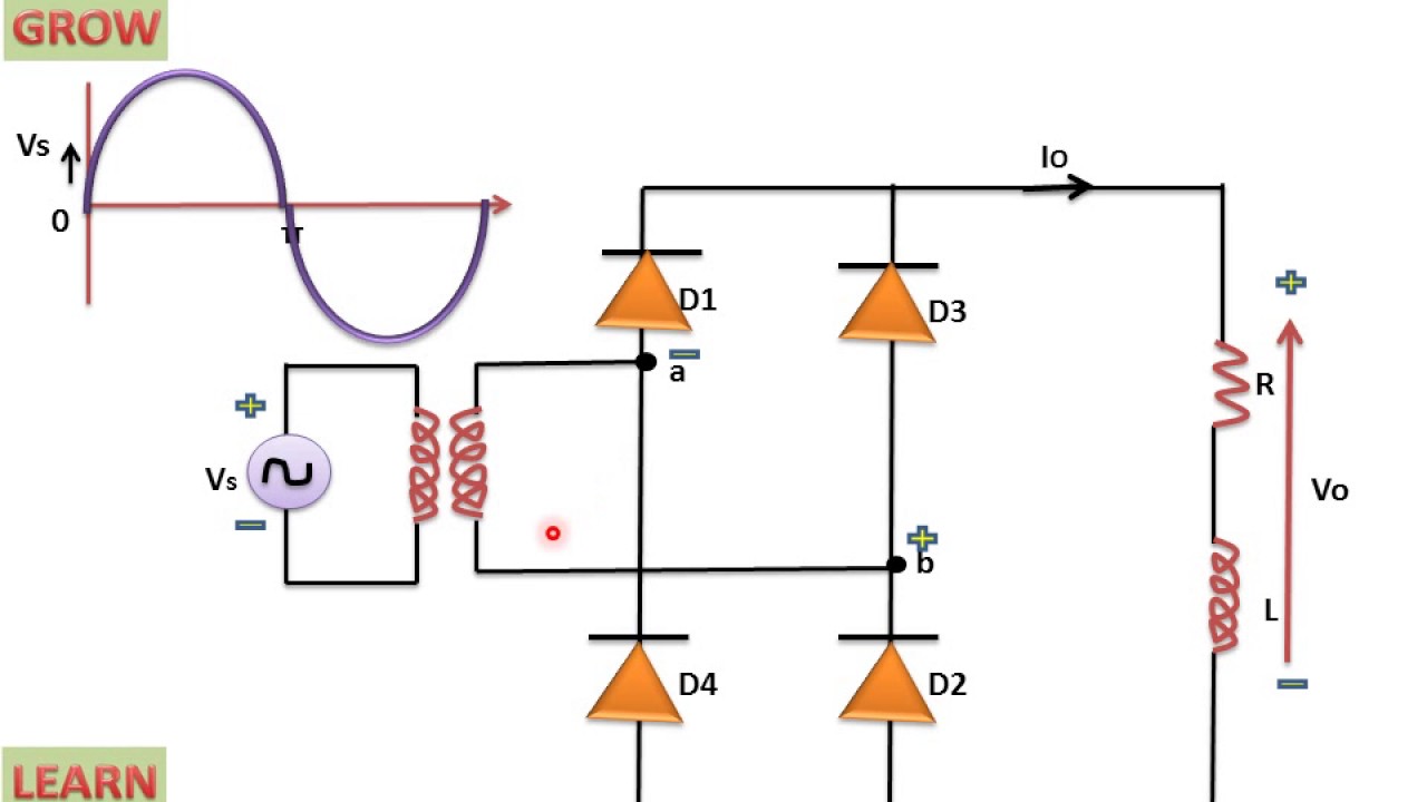
Single Phase Full Wave Rectifier Circuit Diagram

Half Wave Rectifier Circuit Diagram

full wave rectification diagram - Wiring Diagram and Schematics

What is Full Wave Rectifier ? - Circuit Diagram, Working, Advantages
